Hello World (PIC18F57Q43 Curiosity Nano)
Introduction
This tutorial will lead you through setting up a project in MPLabX for the PIC18F57Q43 Devkit and programming it.
Resources
- Microchip
- PIC18F57Q10 Microcontroller
- PIC18F57Q10 Curiosity Nano Board
- MPLabX IDE
Parts Required
| Item | Detail |
|---|---|
| PIC18F57Q43 Curiosity Nano | Website / User Guide |
| Breadboard | |
| USB-C Programming cable |
Critical Information and Concepts
Before working through the tutorial, it is important to answer some key questions about the board. Open up the curiosity nano hardware user guide to find more detailed answers to the following questions:
| Question | Answer |
|---|---|
| What is the difference between the “PIC18F57Q43 microcontroller” and the “PIC18F57Q43 Curiosity Nano”? | The curiosity nano is a 64-pin PCB with an on-board USB connector for programming and communication, microcontroller, external crystal, user-programmable pushbutton and LED, and pre-configured, adjustable power. The microcontroller is just the chip – it needs external circuitry provided by the board, or by the designer to function. Look up at the resources section for more information about each |
| How do you power the curiosity nano? | The curiosity nano may be powered externally (see section 3.3.2), or directly from USB. USB power feed into an on-board, adjustable voltage regulator. See section 3.3 about the adjustable voltage regulator and figure 3-4 for the regulator’s block diagram. See figure 3-10 for details about the power pins. |
| How do you adjust the regulator | In MPLabX project settings, or by sending a special command. See section 3.1.3.3 for the USB drive method. |
| How do you program the curiosity nano? | The board can be directly programmed over USB from MPLabX. For details on how to program it with a separate programmer, see figure 3-11. |
| What other features are on-board? | The Curiosity Nano also features a user-programmable LED and pushbutton switch, available for use in your program. |
| When I plug the curiosity nano in, it shows up as a drive. Why? | See section 3.1.3.1 of the hardware user guide for more information about the mass storage device |
| Can I debug my program over USB? | Yes, this is a great feature of the curiosity nano. See section 3.1 for more information |
Instructions
Install MPLabX if you haven’t already.
- Say yes to installing Microchip Code Configurator and the XC8 compiler if asked.
Open up the Curiosity Nano box. Inside the anti-static bag, you should find one curiosity nano board and two 32-pin male headers.
Insert the male headers into the two rows of offset holes running along the board. See figure 4-2 of the hardware user guide to see how to attach the pins.
Solder the pins to the board
Note: Because the holes are offset, this permits the header pins to establish a fairly solid press-fit. Regardless, you should solder the pins to the board, since you will be using it all semester.
plug the USB cable into the curiosity nano, and then plug the other end of the cable into your computer.
In MPLabX, select File $\rightarrow$ New Project to create a new project.
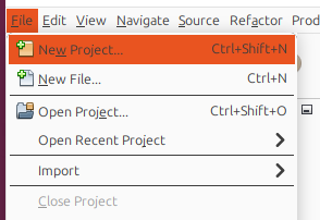 Create a new project
Select Microchip Embedded as the category and “Application Project(s)” from the Projects list
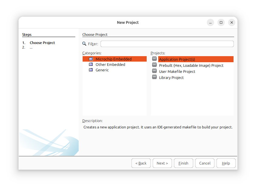 Select “Application Project(s)”
Select the PIC18F57Q43 as the “device” and the PIC18F57Q43 Curiosity Nano as the programmer
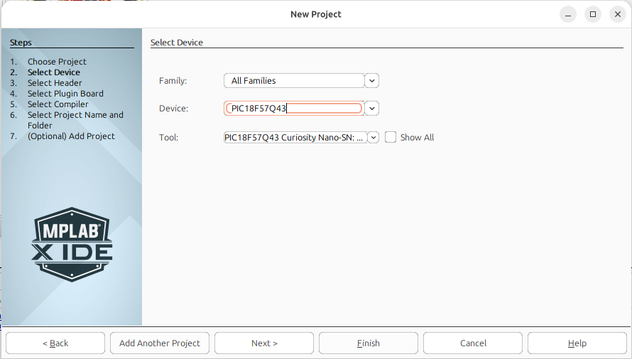 select the appropriate device and programmer
Select the XC8 compiler
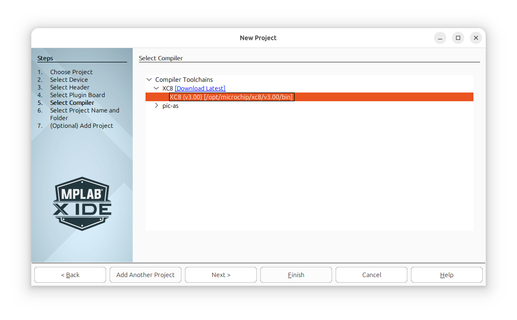 Select the XC8 compiler
Name your project something like “hello-world-uart” and select your project’s parent directory.
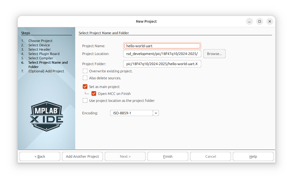 provide project details
Your project will open. Select “next” to create a MCC profile using “Melody”, the current MCC engine.
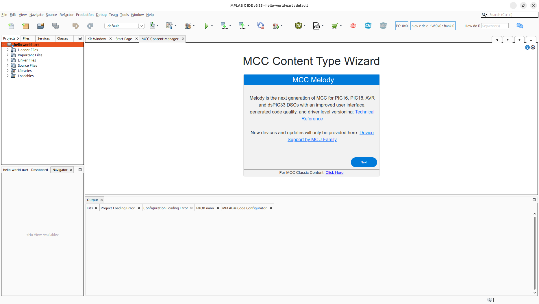 Select next
Based on the device settings entered during project creation, MPLabX may need to download additional files. Wait for this process to finish. (Ensure you have an internet connection or the process may not work)
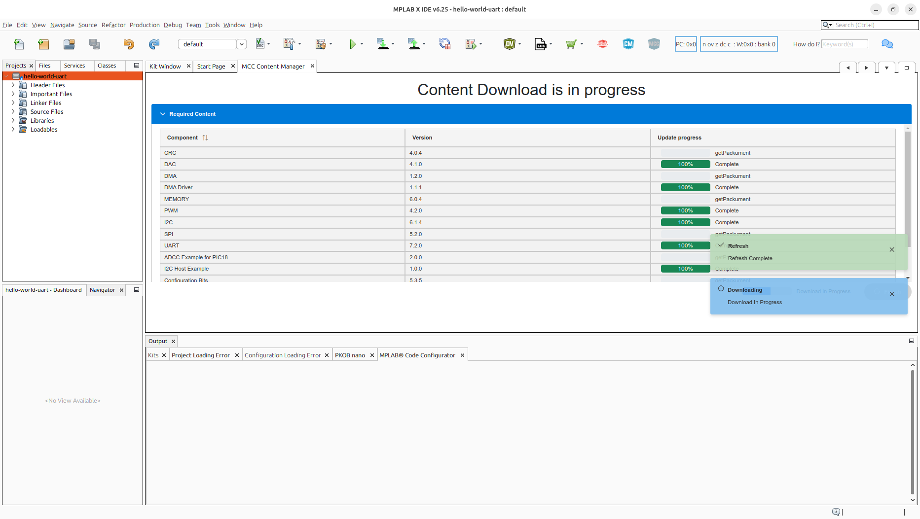 Download Support Files
MCC Should open.
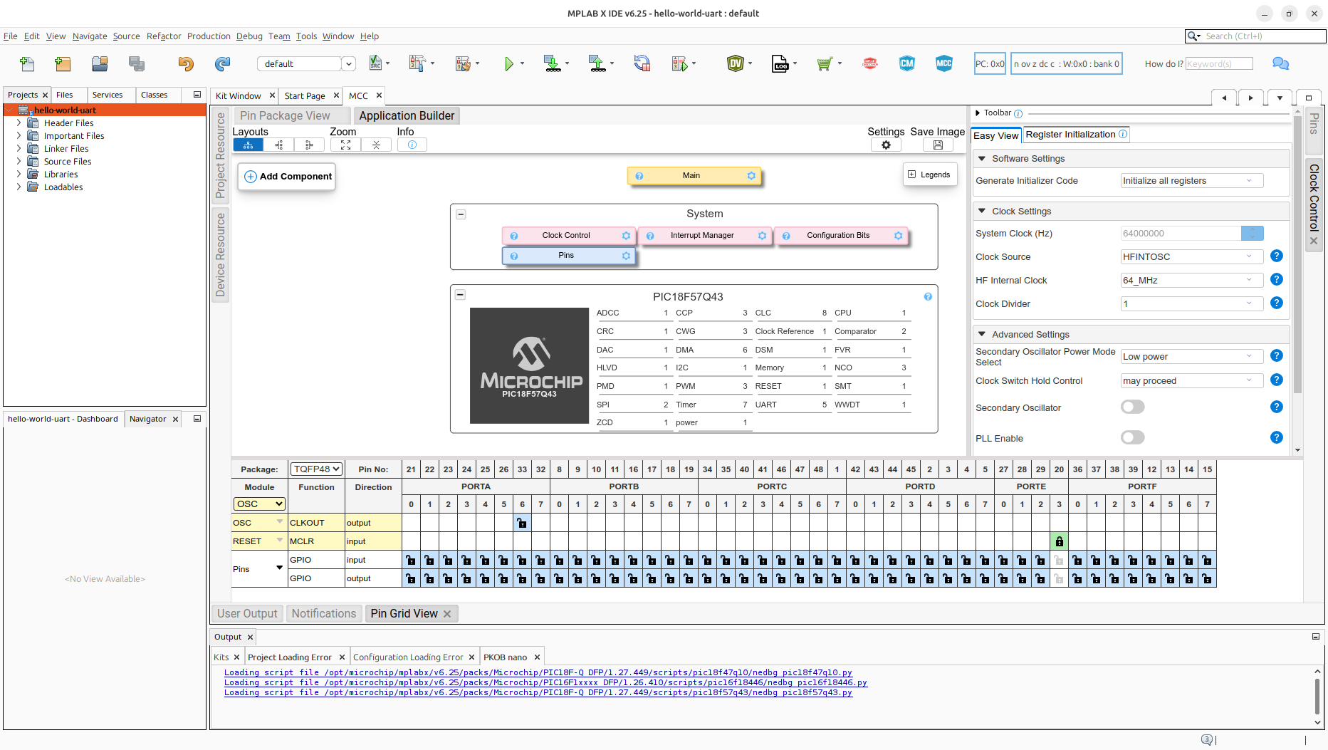 MCC Configuration View
In the pins window, click on port F3 in the GPIO output row to enable RF3 as a digital output.
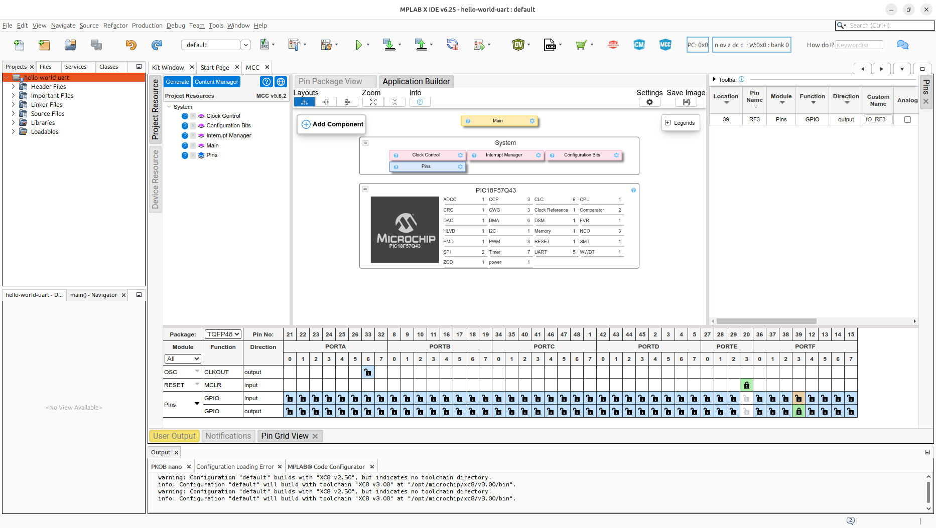 Add an Output
Click the “generate” button to generate your MCC configuration
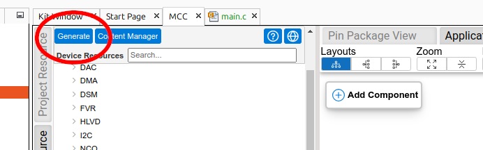 generate MCC
Open main.c in the project explorer. Inside the curly brackets after the
while(1)statement, insert__delay_ms(500); IO_RF3_Toggle();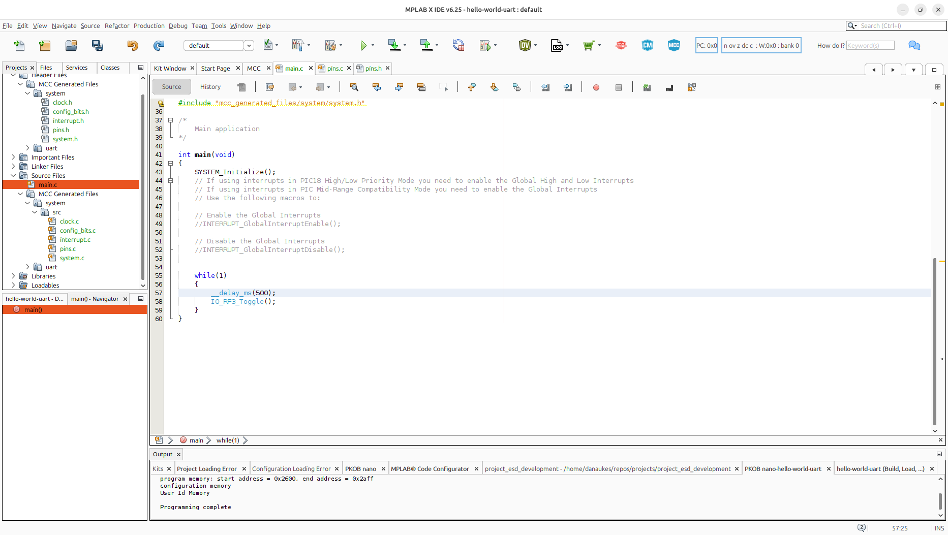 modify code
Select the “clean and compile” button to verify your project compiles.
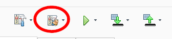 Clean and complile
Why Clean and Compile? After generating a new MCC configuration, MCC generates the code necessary to support those changes. Cleaning your build files before compiling will ensure that old symbols are removed in the case that subsystems were removed or swapped out in MCC
Select the “download” button, ensuring your Curiosity Nano device is connected.
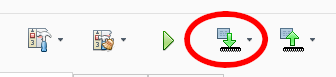 download code
Observe what happens.
Continue on to the next tutorial, Enabling UART in MPLabX