Electrical Rules Check (ERC)
Introduction
In the last tutorial you created a schematic. But is it any good? The electrical rules check, or ERC, is a useful way to debug your circuit. This example tutorial takes you through the process of finding and eliminating circuit design errors.
Resources
Steps
Open up the adjustable voltage regulator circuit from the previous tutorial.
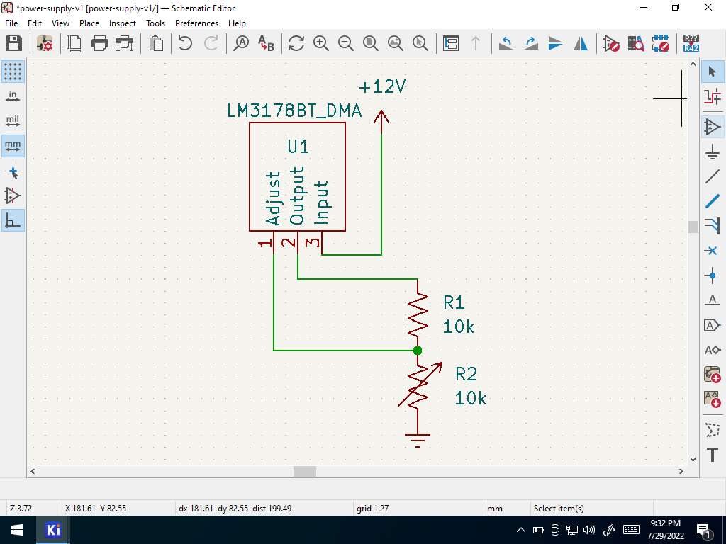 Prior Schematic
Go to inspect –> “electrical rules checker” in the menu.
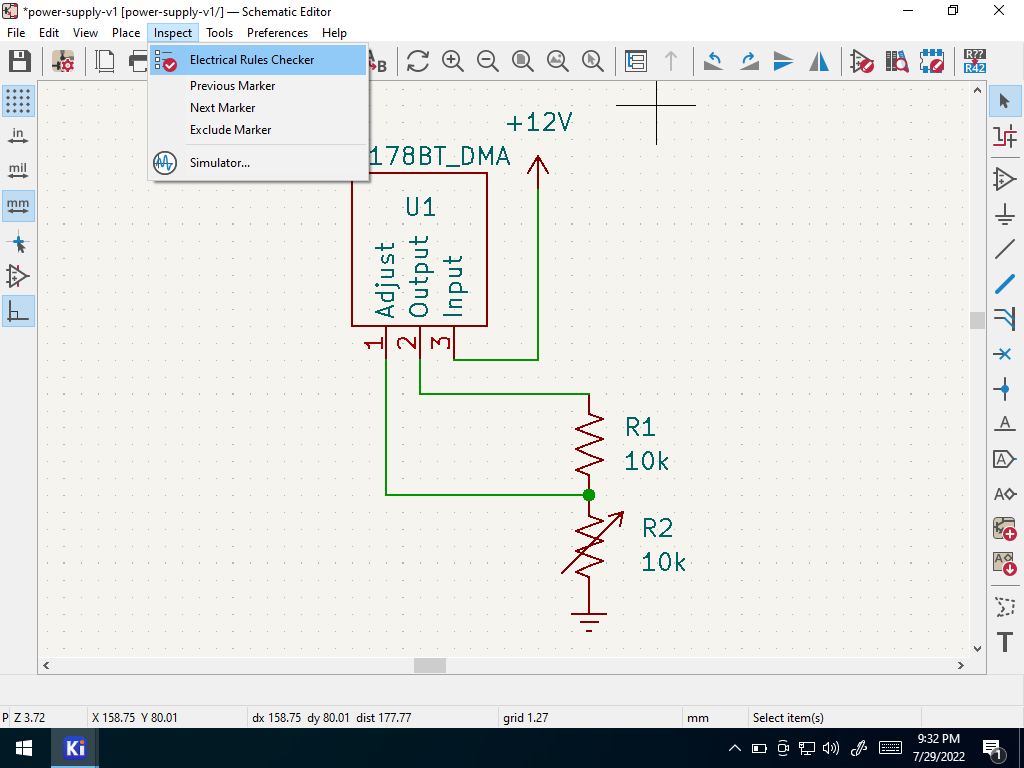 Open ERC
Select run and inspect the results. There should be two errors.
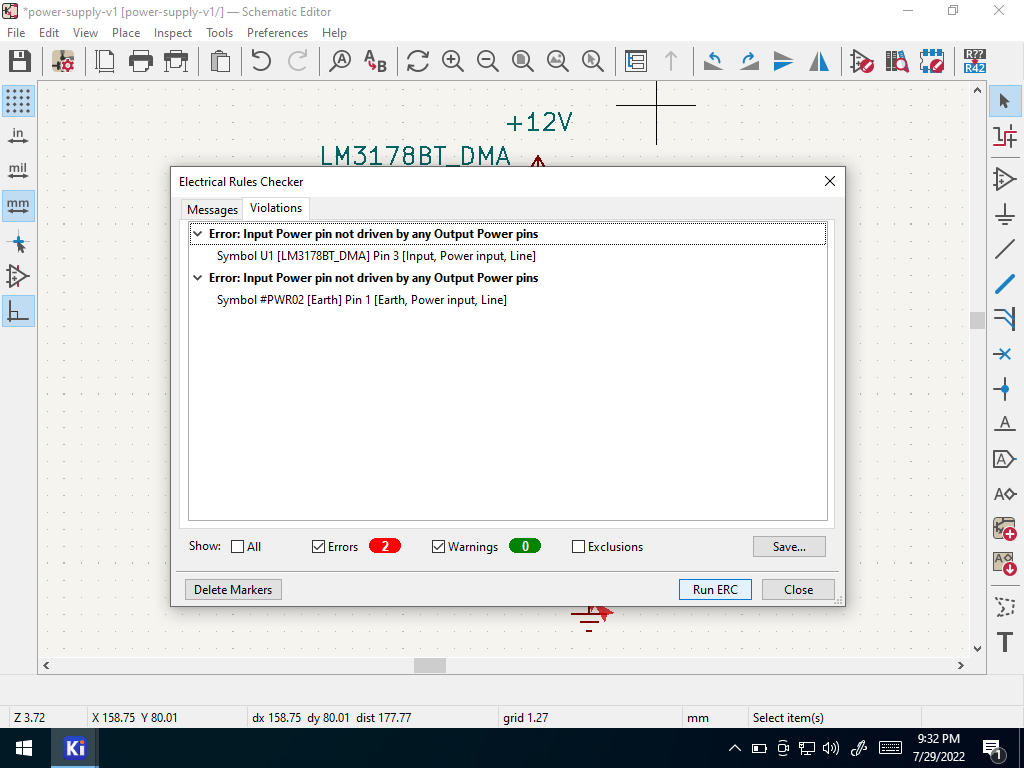 Two Errors
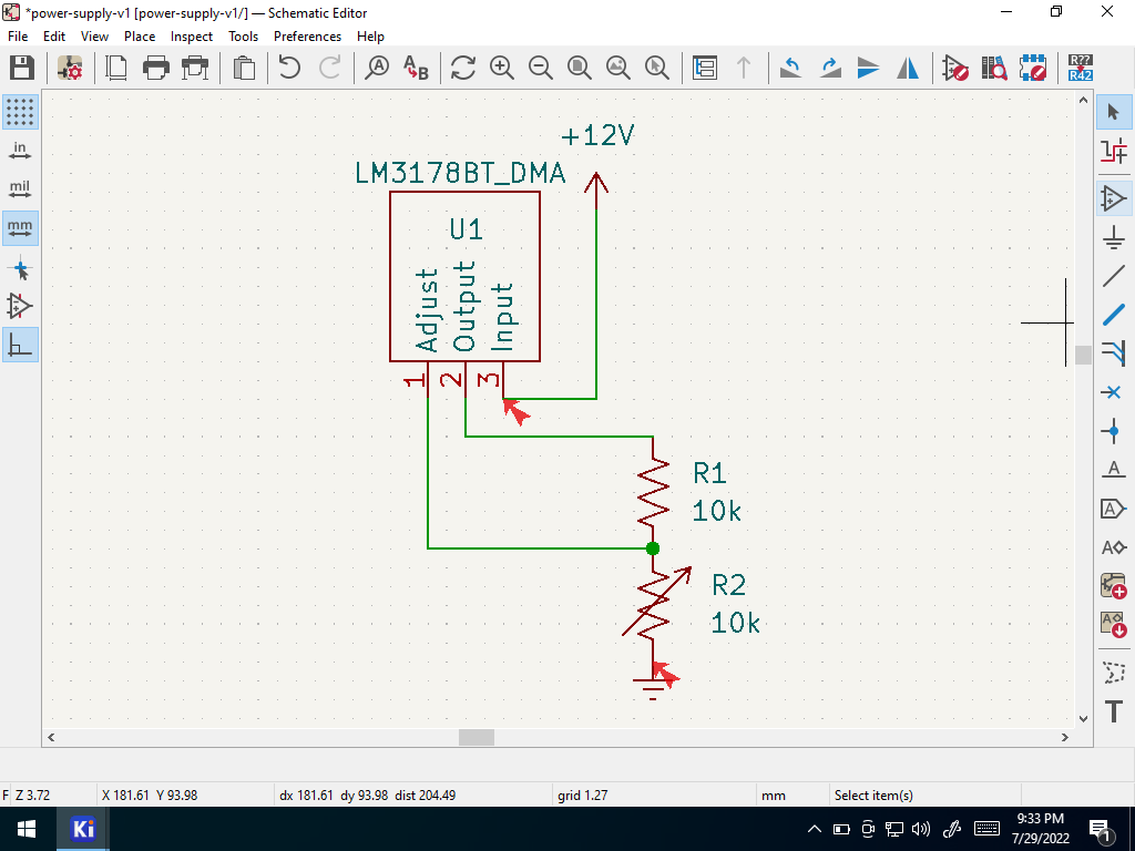
These errors indicate that the 12V and ground power connections are not connected to a source. Which is true! We forgot to add an external power connector to the board design, as in power from the wall or from an off-board battery!
These errors can be resolved by adding a power connector. Select add part
 Add Part
Search for “screw terminal” and select the 1x2 version (one row, two positions).
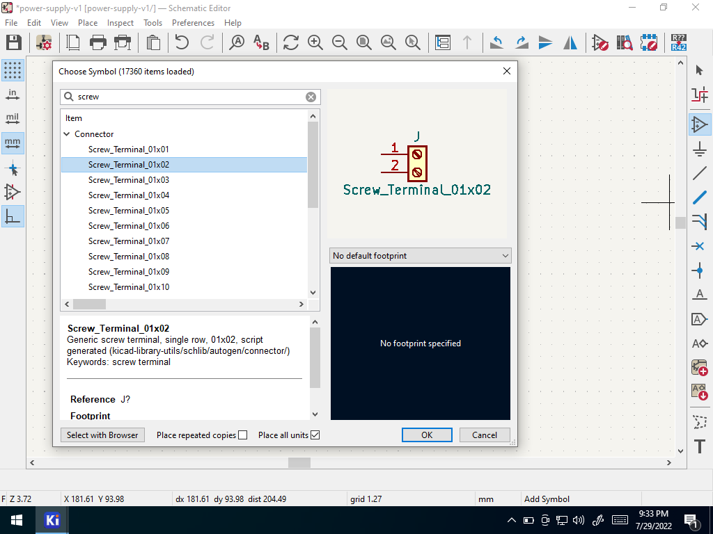 Select a screw terminal
Place the screw terminal and wire it up
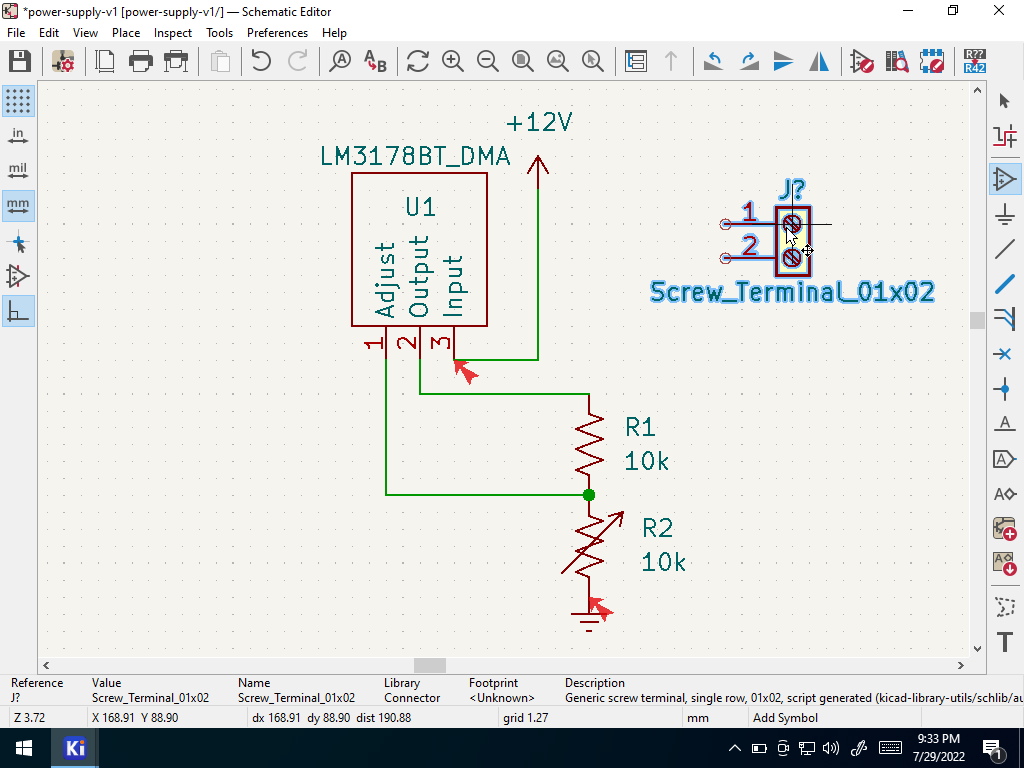 Place part
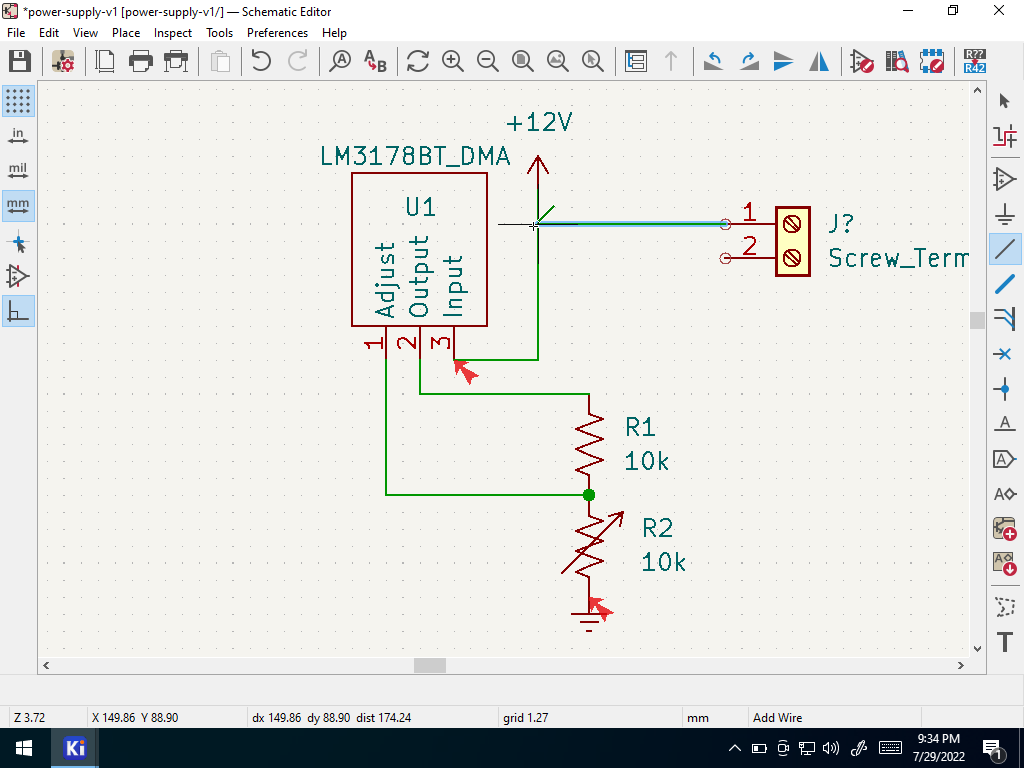 Wire it
Because the 12v and ground symbols are “power ports”, you can use as many of them as you want in your schematic, because they all signify the same thing, rather than a copy. So for the purposes of ERC, place a separate ground symbol (the same symbol as you used before) near the second pin of the screw terminal and wire it up.
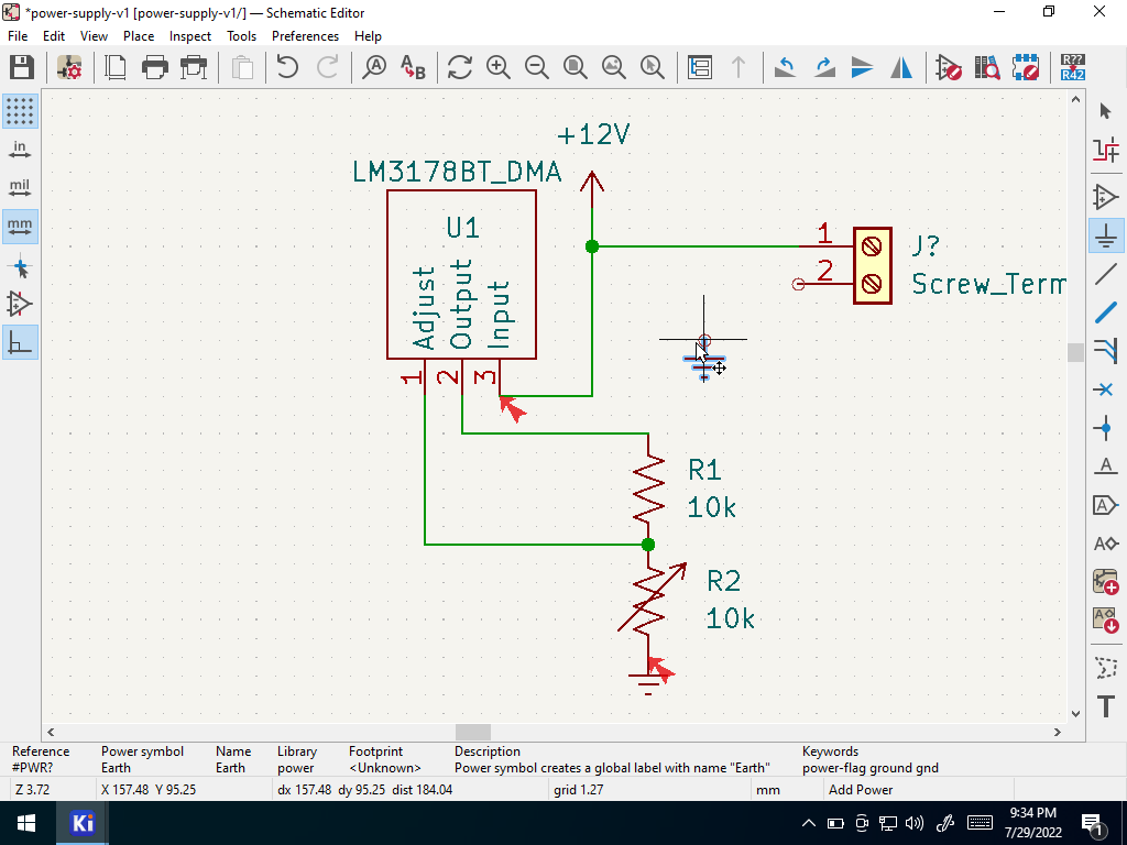 Add GND
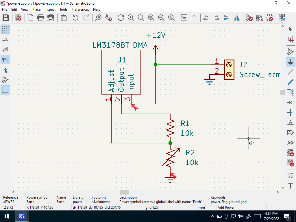 Wire GND
Run Annotations (assign reference designators)
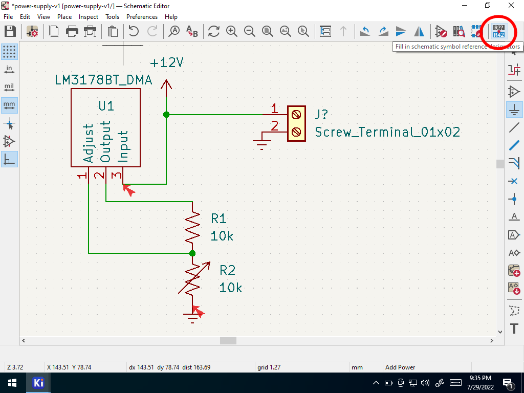 Run Annotations
Run ERC again
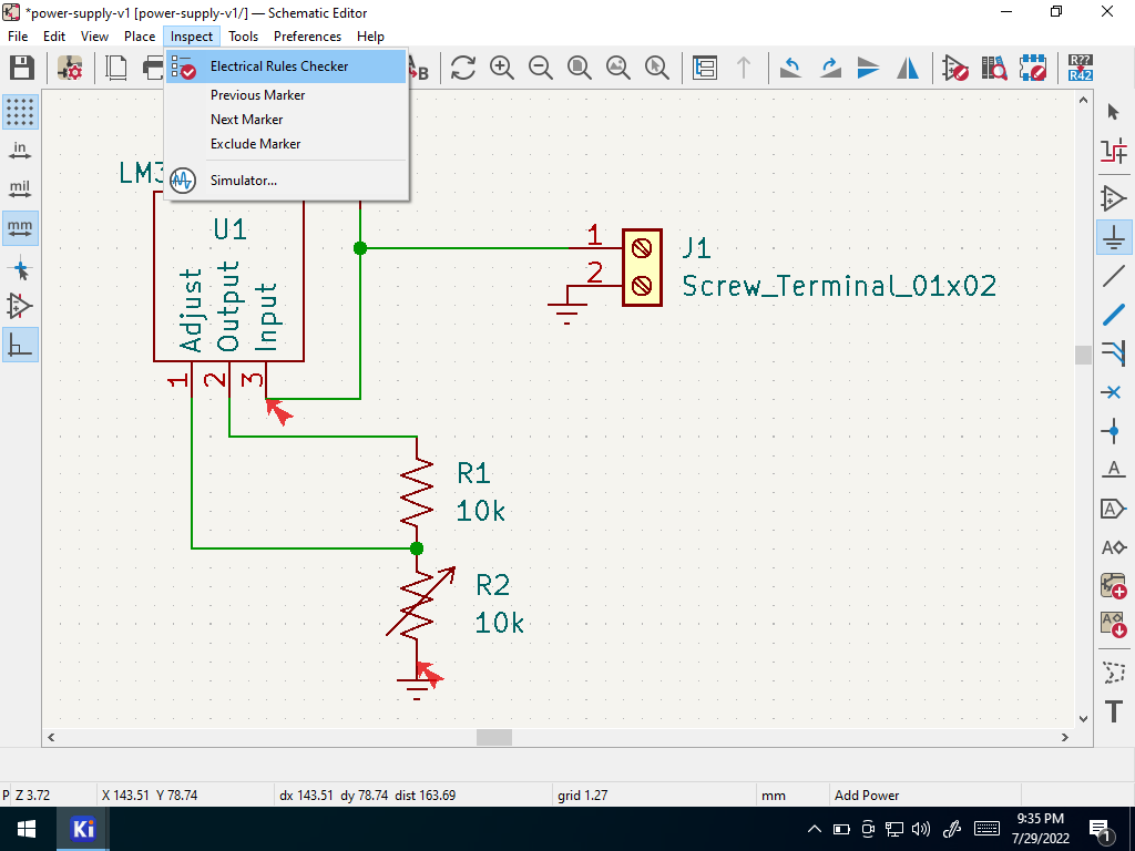 Open ERC
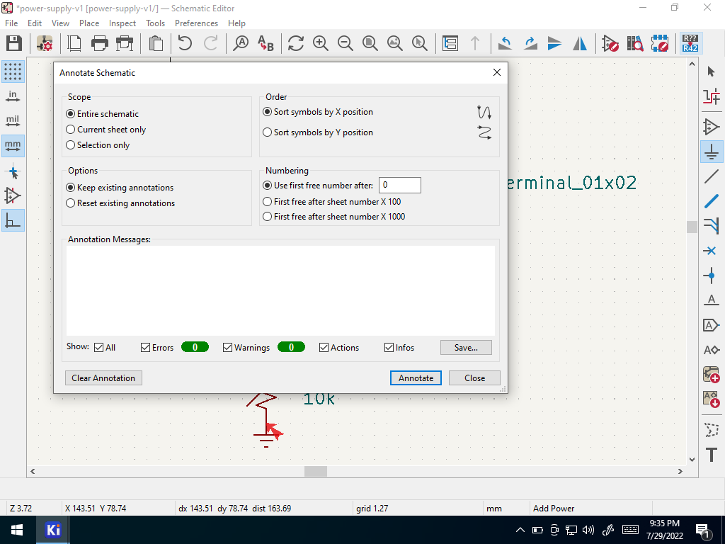 Run ERC
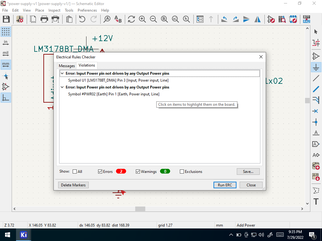 See Errors
Why are there still errors? The screw terminal pins are “passive” pins; they don’t indicate a power connection. To solve this you must explicitly state that pins 1 and 2 of the screw terminal are power outputs.
Double click on the screw terminal
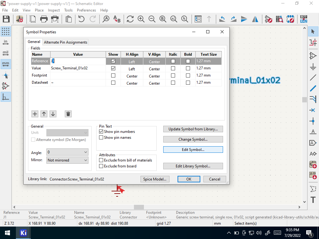 Open Symbol Properties
Click Edit Symbol
Editing a symbol of a built-in library directly from within a schematic will only impact that schematic; it will not be propagated back to the library.
Change pin 1 and 2 to “power output” types
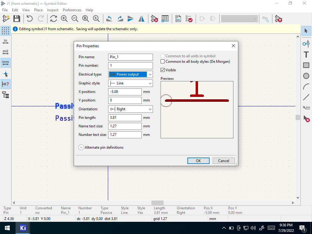 Select Power Output
Save and close the symbol editor window.
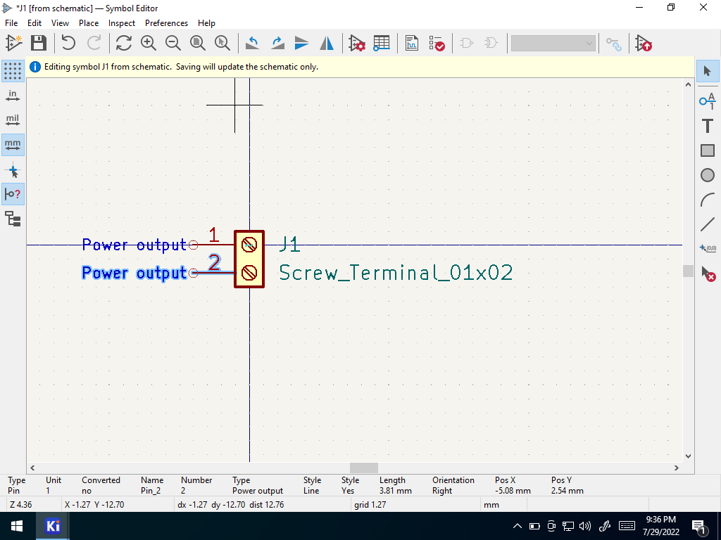 Save Symbol
Re-run ERC one last time
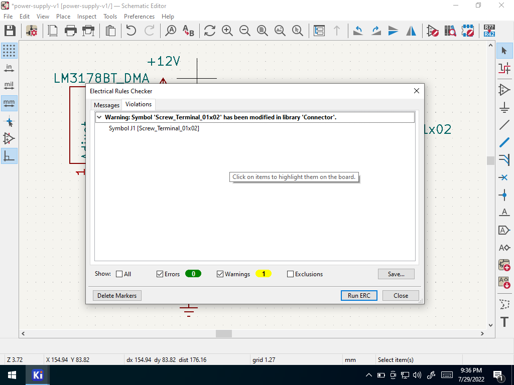 One Warning
The one remaining warning indicates that you have locally edited a symbol within the schematic. This was intentional in our case, and can be ignored.
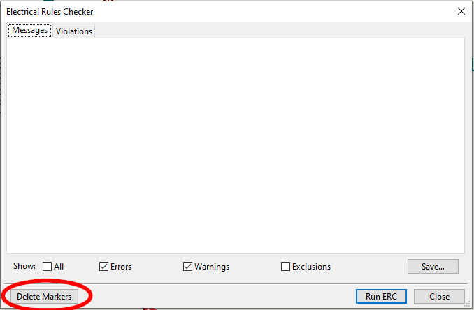
Delete Markers
You can delete the markers (little arrows in your schematic) generated by ERC by opening up the ERC tool and selecting the “delete markers” button
 |
|---|
Delete Markers |