Symbol Creation
Introduction
Resources
Steps
Open up KiCad (start –> KiCad) and select the Symbol Editor
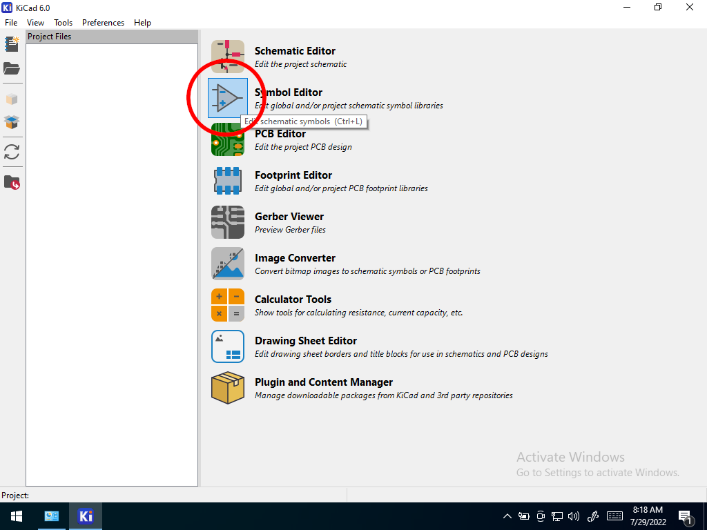 Open Symbol Editor
If this is the first time running the symbol editor, you will be asked to configure the global symbol library table. Select the default option.
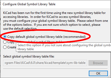 Configure Global Symbol Library Table
Select File–>New Library
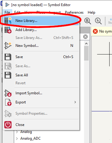 Step 2
When you start a new library, a popup window asks if the library will be global or project table entry. Global should be chosen.
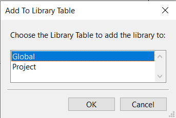 Select Library Type
Note: Custom libraries must be copied as “new project table entries” into the project folder after being fully populated but before archiving.
Give the library a name unique to yourself
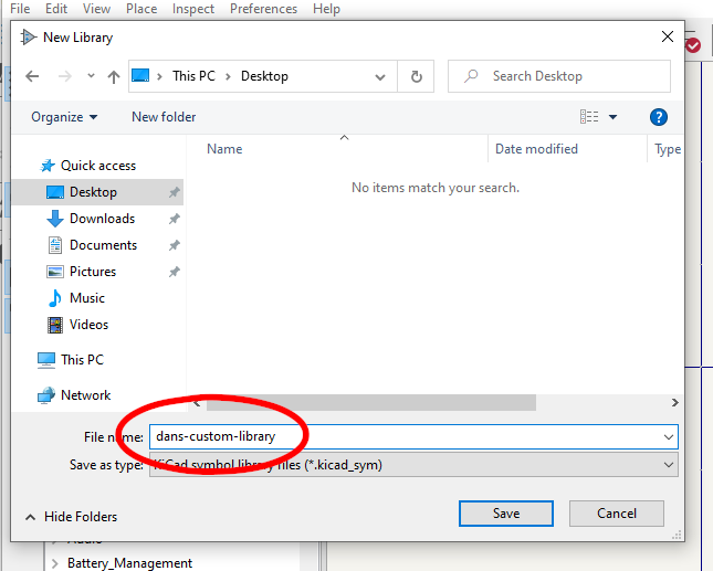 Name your library
In the main editor, create a new symbol
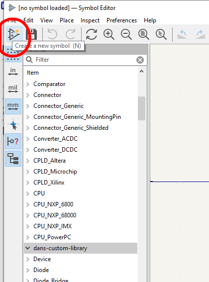 Create new symbol
Fill in Symbol information
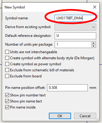 Fill in Symbol Info
Create a rectangle
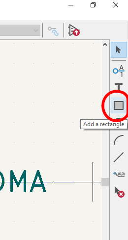 Create a Rectangle
Place the rectangle in the working area. It doesn’t have to be precise yet.
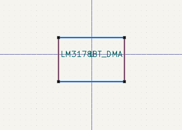 Place Rectangle
Create a Pin to go along the bottom of the part (similar to its package)
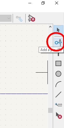 Create a Pin
Fill in Pin information, including pin name, number, type, and orientation. Refer to the datasheet.
For example, pin one should be an “input” pin
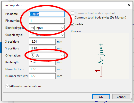 Pin 1
Pin 1Pin 2 is a voltage out pin type
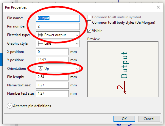 Pin 2
Pin 2Pin 3 is a voltage input type
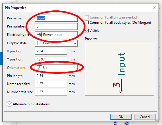 Pin 3
Pin 3
Finally, adjust pins and boxes to get the final look and feel of the device. Select the parts you wish to move, right click and select “move” (or type “m”)
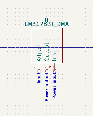 Adjust Pins and Box
Save and Close.