PSoC Hello World Lab
Introduction
The purpose of this lab is to get you through the first steps of opening and using PSoC Creator with either your CY8CKIT-042 or CY8CKIT-042-BLE kit for the first time
Steps
Open PSoC Creator
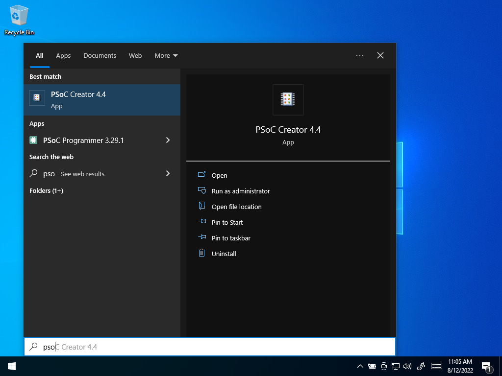 Open PSoC Creator
Select “Create a new Project” in the Start Page
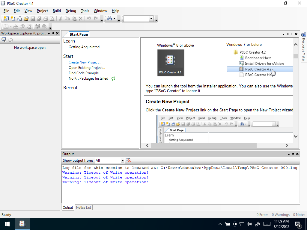 Create New Project
Select Project Type
- Select “Target Device”, select PSOC 4, and then scroll down to “launch device selector…”
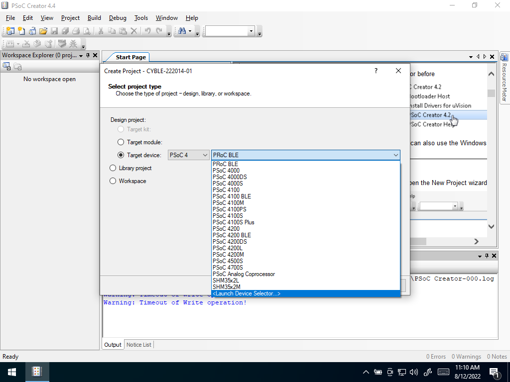 Select Device
In the device selection window, scroll down and look for the device you are using. You will have to look at the chip on your board. For the Pioneer Kit, this is the black chip in the center of the board. For the BLE version, this is the diagonal black chip on the daughter board. The chip is noted in the white silkscreen layer directly below it. For the most recent versions purchased in the class, these correspond to:
- PSoC 4 Pioneer Kit: CY8C4245AXI-483
- PSoC 4 BLE Kit: CY8C4248LQI-BL583
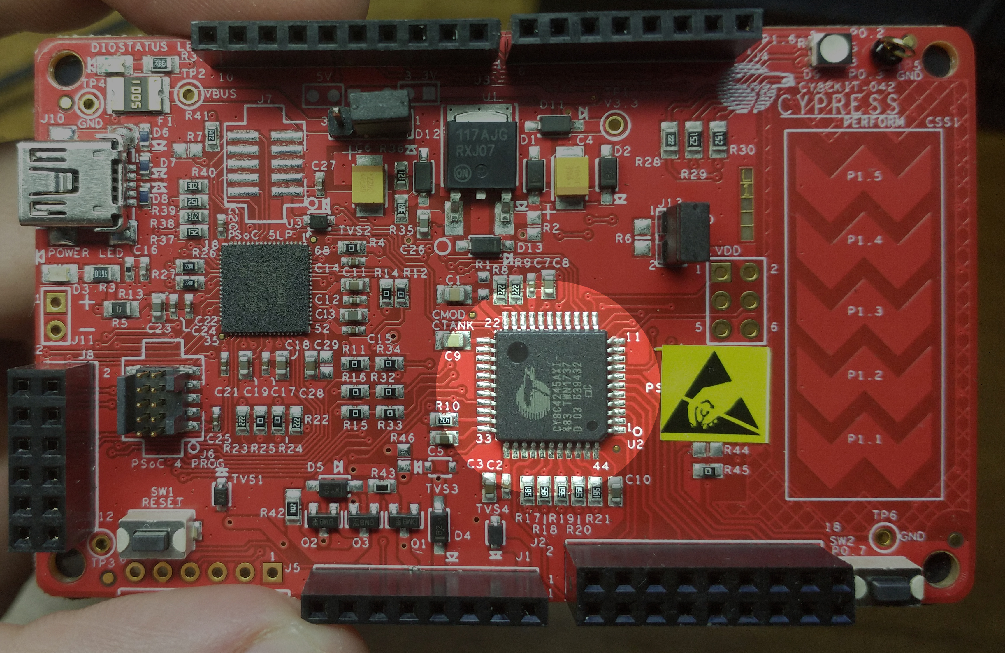 Pioneer Chip Location
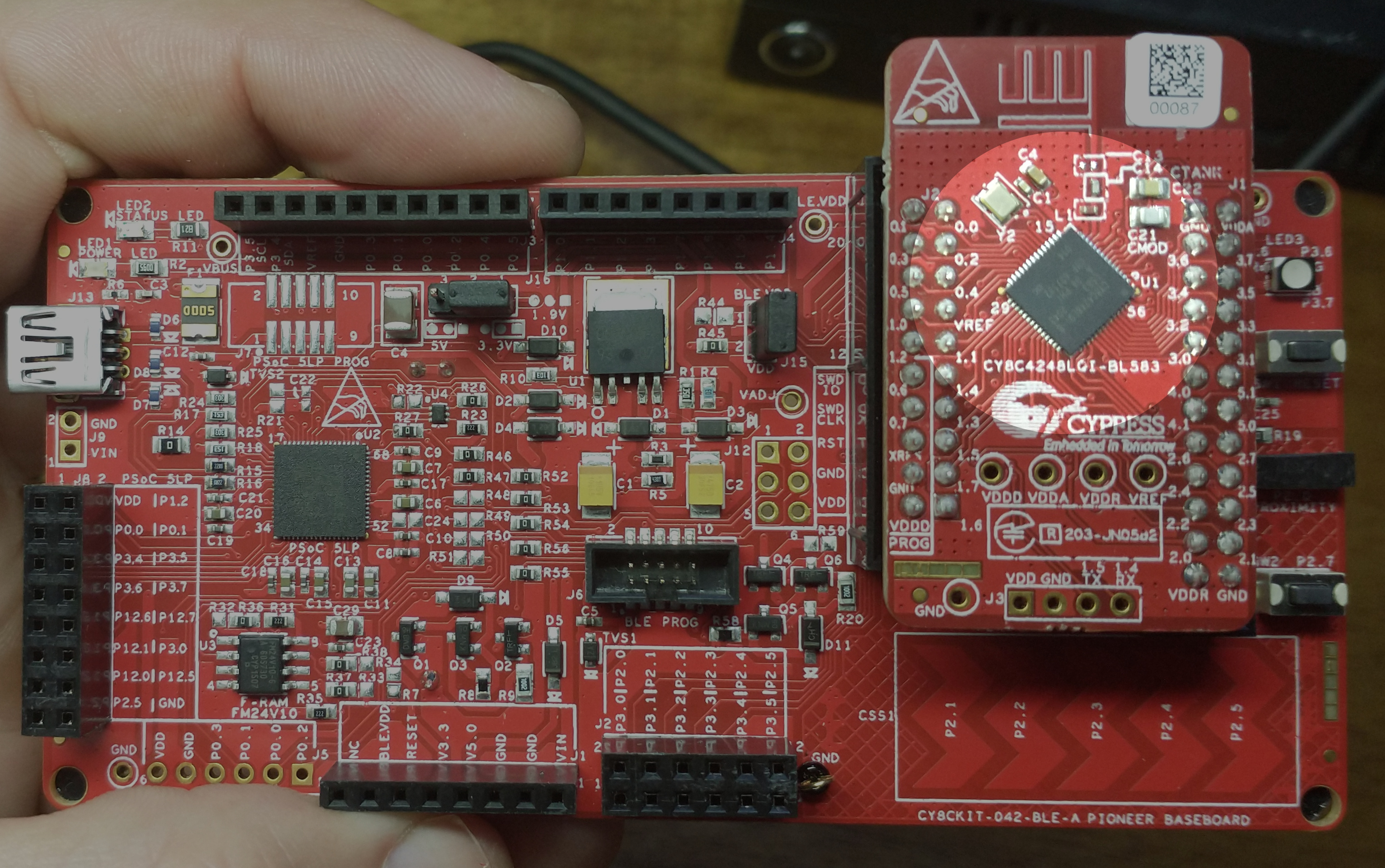 Pioneer BLE Chip Location
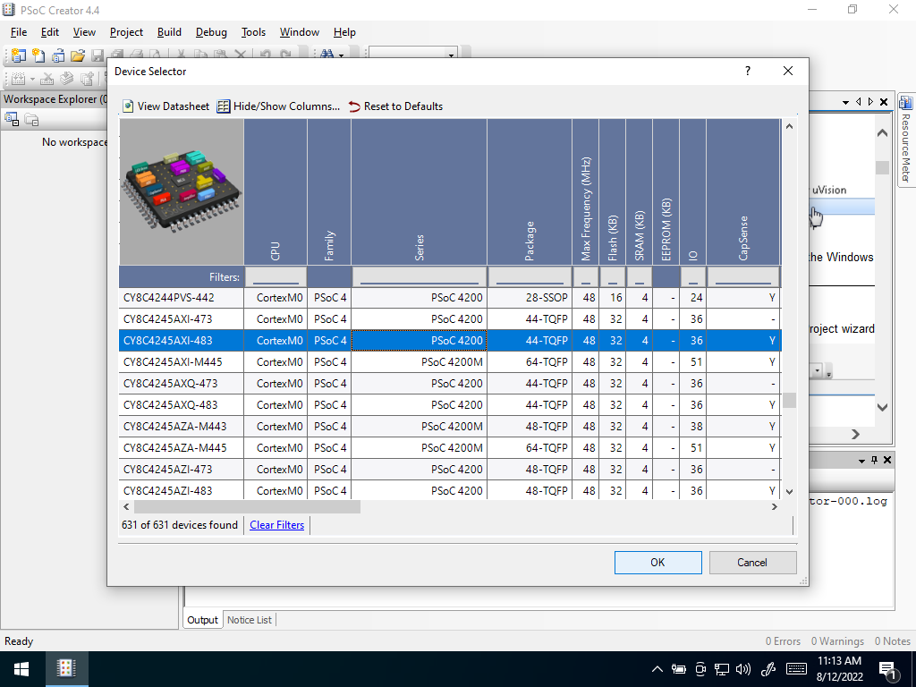 Device Selector
Once you have selected the right part, click “next”
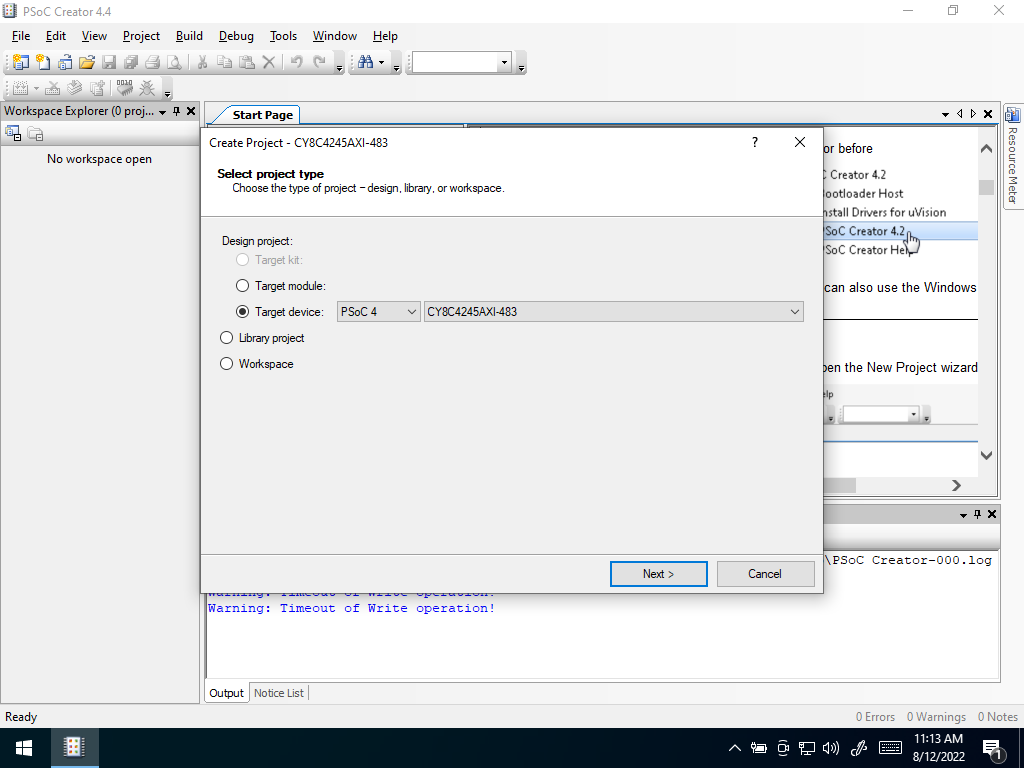 Select Next
Select “Empty Schematic”
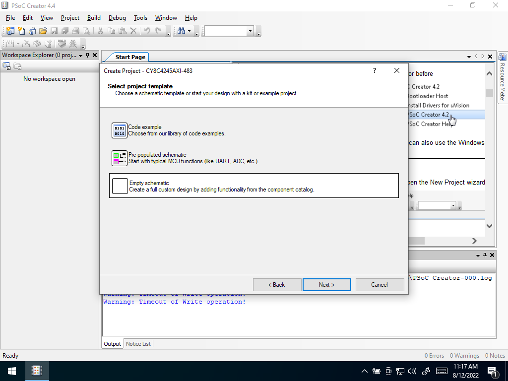 Empty Schematic
In the next window, define a new Workspace (something like “RAS304-Lab2”). Name your project (something like “flash-led”). Wait for the workspace to open and populate with your “top design”.
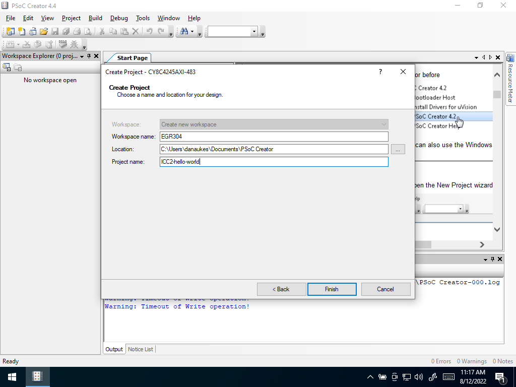 Name your workspace and project
In the “Component Catalog” window on the right of the screen, open up “Ports and Pins” and select “Digital Output Pin”. Drag the item into the “schematic view” in the middle of your screen
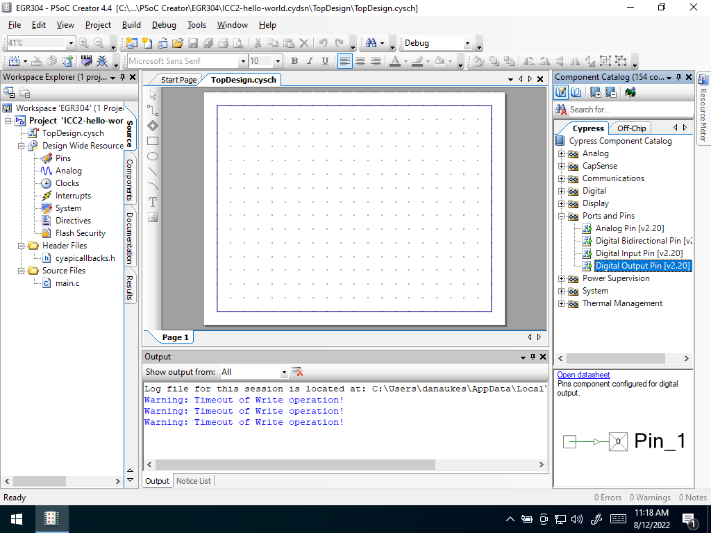 Select “Digital Output”
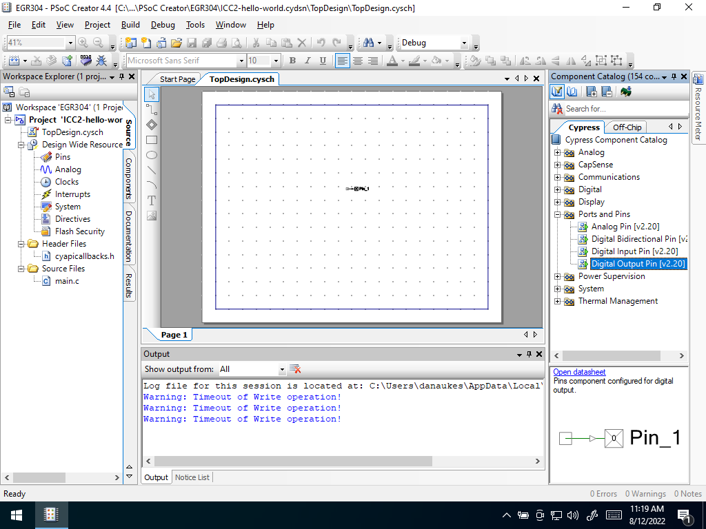 Drag to schematic
Zoom in on the pin component and double-click to configure it. A dialog will pop open. Rename the pin to “Pin_Red”. Deselect “HW Connection” checkbox. (This allows this setting to be controlled by software rather than be “hard coded”). Accept changes by clicking “ok”.
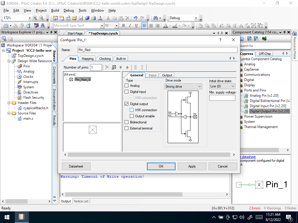 Configure digital output
Scroll to the “Workspace Explorer” on the left side of PSoC Creator. This window shows resources available to the project. Click on the “pins” icon to further configure the input/output (i/o) pins
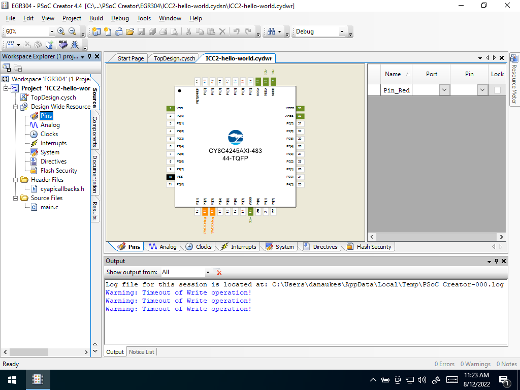 Configure Pins
Map the “Pin_Red” digital output you just configured to a physical pin of the device. In the right hand side of the window, a tab named “pins” can be seen. Click the port column of the “Pin_Red” row to set the physical pin you plan to use.
- In the Pioneer Kit, this pin is P1[6].
- In the Pioneer BLE Kit, this is P2[6].
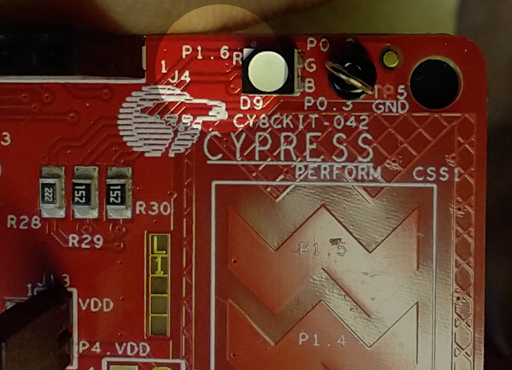 Pioneer Pin
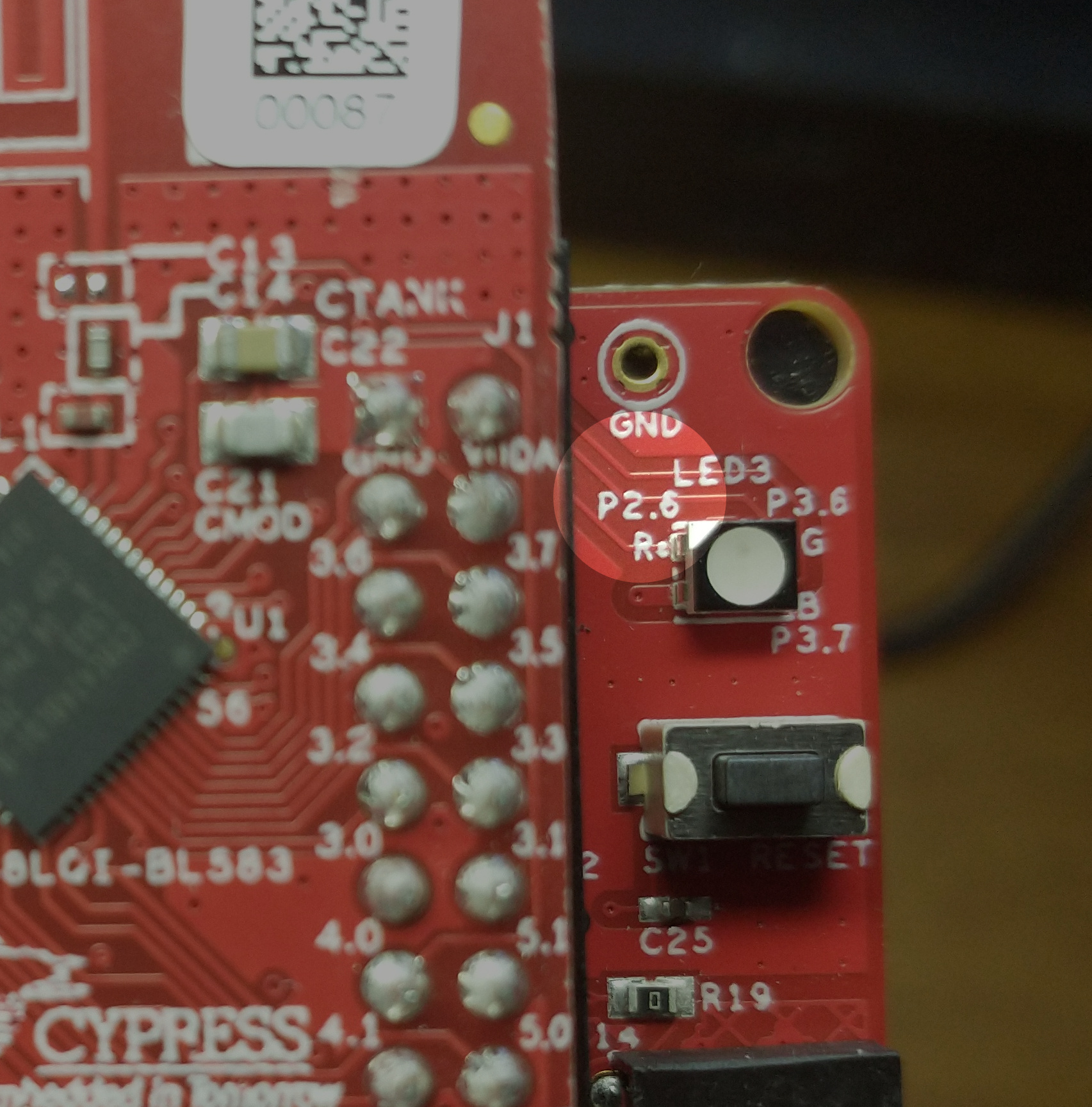 BLE Pin
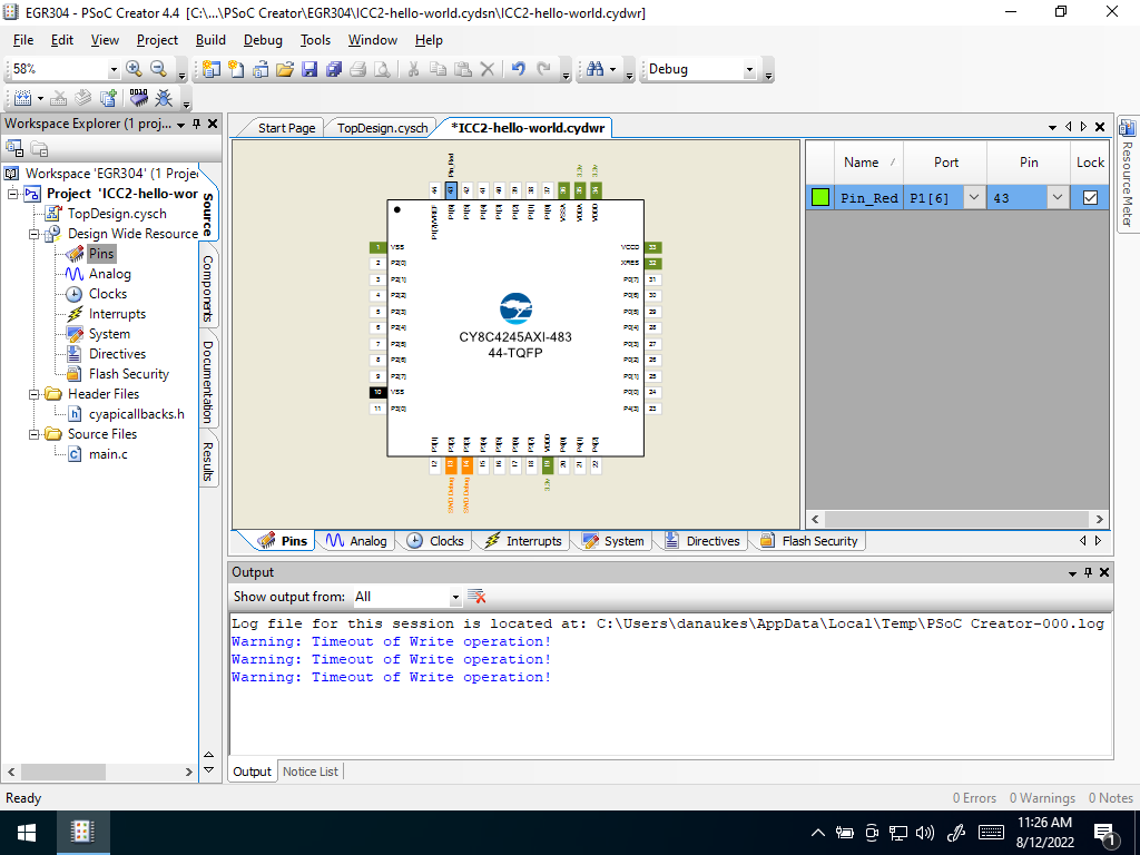 Map Pins
From the workspace explorer window, click on “main.c” to open it
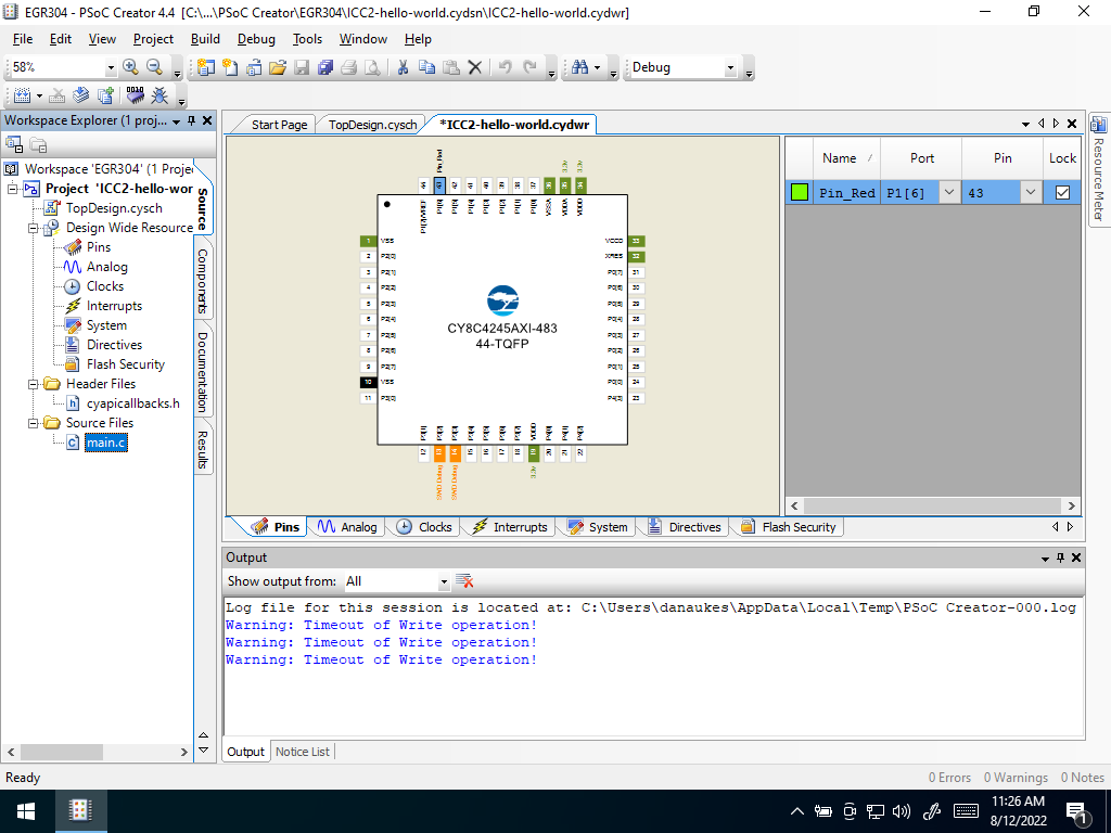 Click on main.c
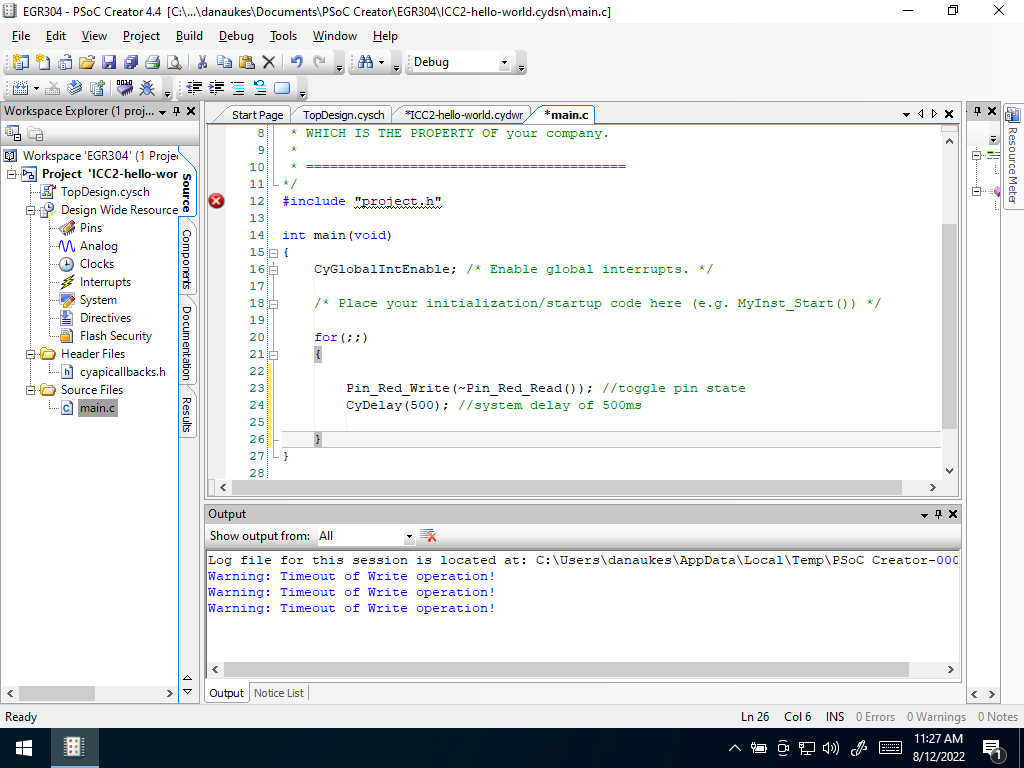
Once it opens, add the code shown below inside the
for(;;)brackets to toggle the LED pin once every half second. The below code reads the pin’s current value and writes its inverse back to the pin, followed by a 500ms delay.Pin_Red_Write(~Pin_Red_Read()); //toggle pin state CyDelay(500); //system delay of 500ms
 |
|---|
Add Code |
Press the “Program” button on the PSoC Creator toolbar to build the project and program your kit. In the Debug type window, you may need to select “port acquire” and then select the PSoC and select ok
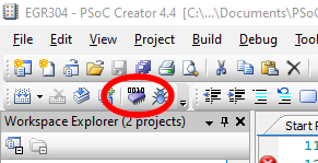 Program Button
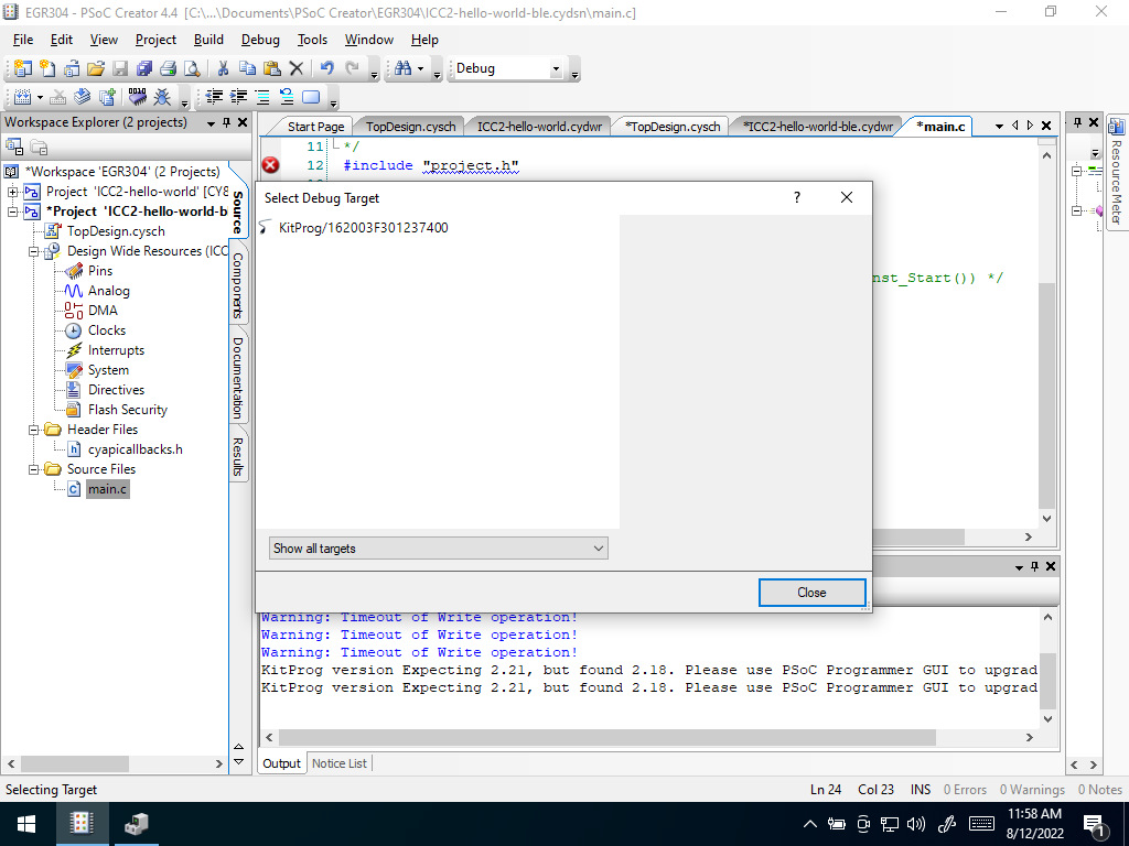 It should look like this
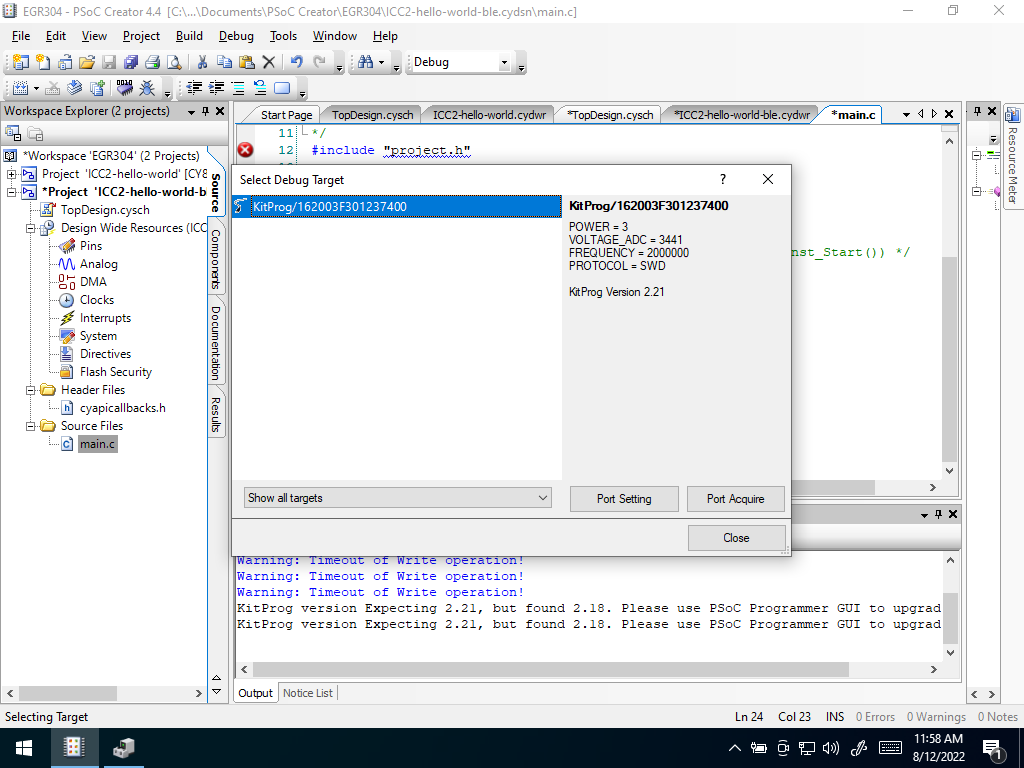 Port Acquire
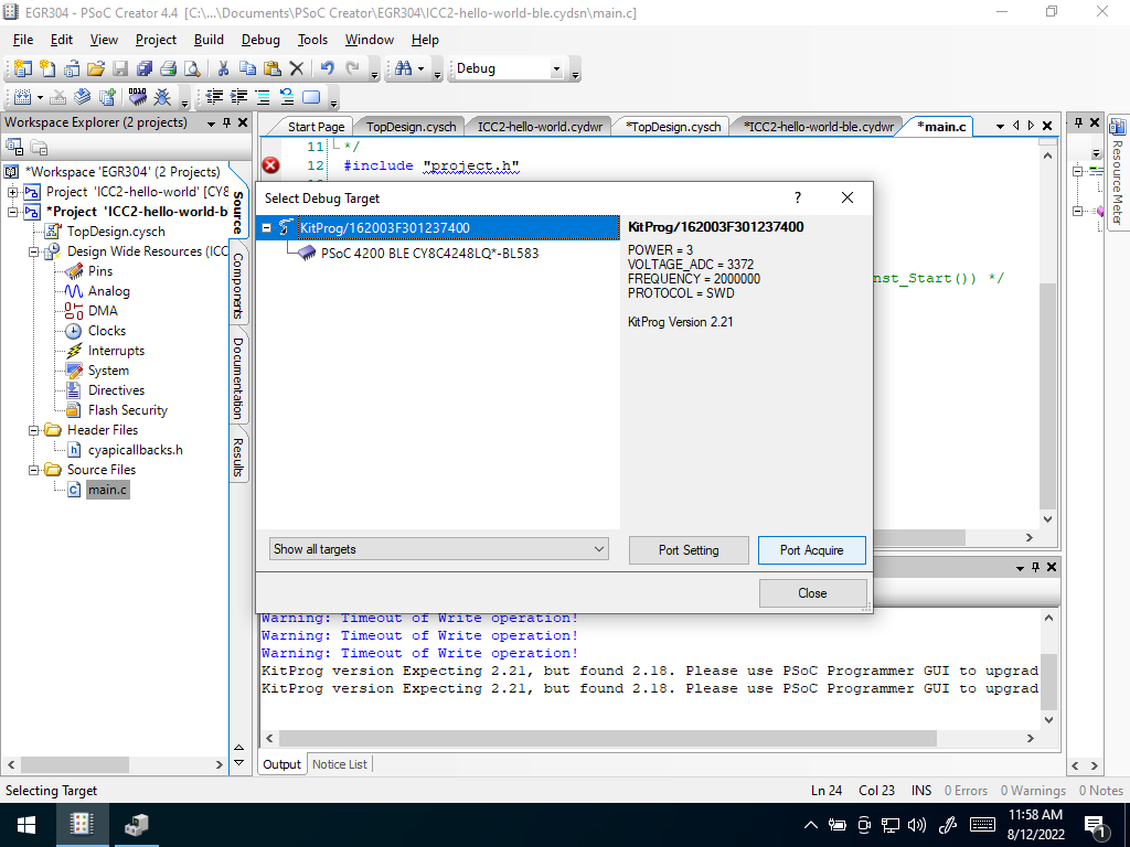 Port Acquire 2
If this is the first time programming your kit, you may get a message asking you during debug target selection to upgrade firmware. If this happens:
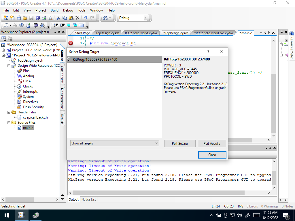 Upgrade Firmware Message
- Close the “debug selection” popup and, from the start menu, open “PSoC Programmer” (Start –> “PSoC Programmer”). You should get a similar message.
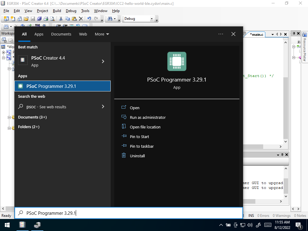 PSoC Programmer
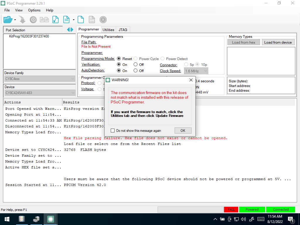 Programmer Firmware Message
- click ok and switch to the firmware tab. Select “update firmware” and follow the instructions
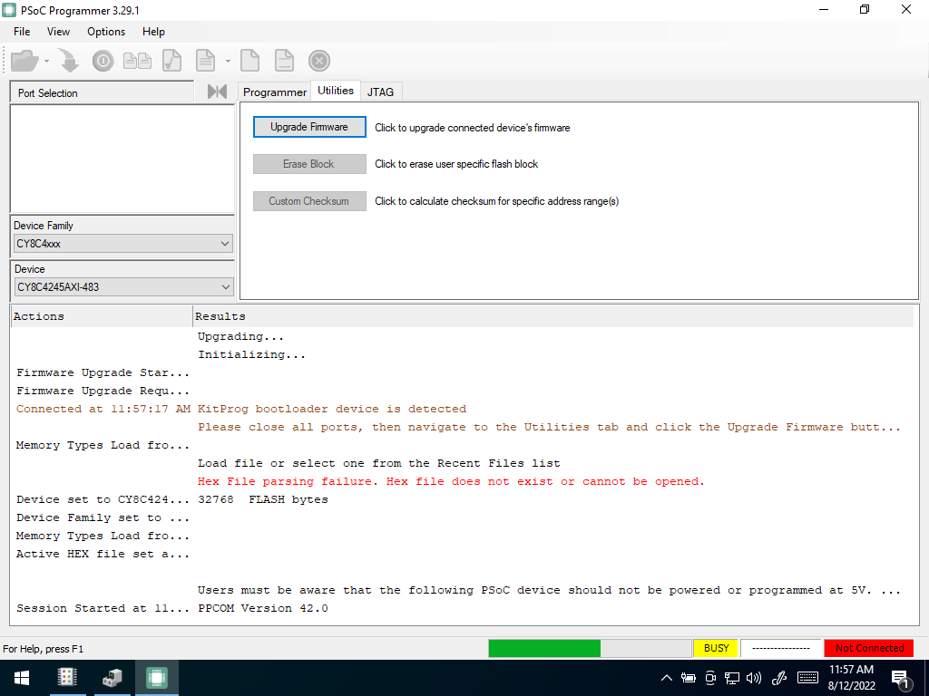 Upgrade Firmware
- once complete, close PSoC Programmer
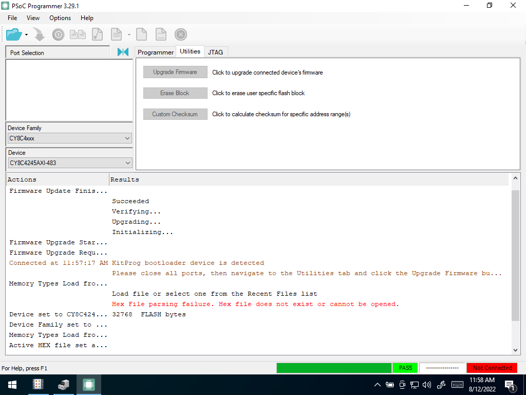 Finished Flashing
- Press the “Program” button on the PSoC Creator toolbar to build the project and program your kit. In the Debug type window, you may need to select “port acquire” and then select the PSoC and select ok
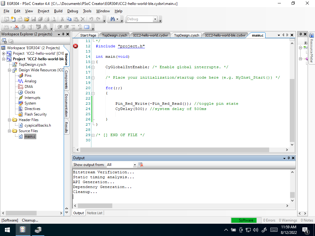
It should look like thisPort AcquirePort Acquire 2The progam will then compile. The results of the build and program operation will appear in the “Output” area at the bottom of the PSoC Creator IDE. Once programmed, the red LED on the kit should start blinking at a 1 Hz rate, at 50% duty cycle.
 |
|---|
Compile |